The goal of this tutorial is to set up a lantern object which casts soft dynamic shadows from the solid parts of the lantern.
The two normal ways of creating detailed shadows are to either bake them with static lights (which will not work for a moveable light source), or to use Raytraced Distance Field Soft Shadows, which don’t work very well if the light source is actually inside the model which is supposed to cast the shadow.
Instead of either of those, I will explain how to solve this problem by using a light function.
A light function is a material shader that can filter the intensity of light being output by a light source. It can be used to give the light different intensities at different angles, with the output of the light dependant on the colour of the material, from black (no illumination) to white (full illumination).
We will use this to effectively mask the parts of the light where we don’t want it to shine at full brightness.
Further, we will blend between two different masks depending on the distance, giving a more realistic effect where the shadows are fairly sharp close to the light source, but get softer as the distance increases.
Contents
Requirements
This tutorial will need the following tools:
- A 3D modelling package
- An image manipulation tool (IrfanView is suggested, as I have included a batch script which makes use of it to automate some steps.)
- AMD CubeMapGen
The model
The first step is to create the model that you wish the light source to be inside. That is a very complicated subject, far beyond the scope of this tutorial.
I will be using this miner’s lamp as the example model.
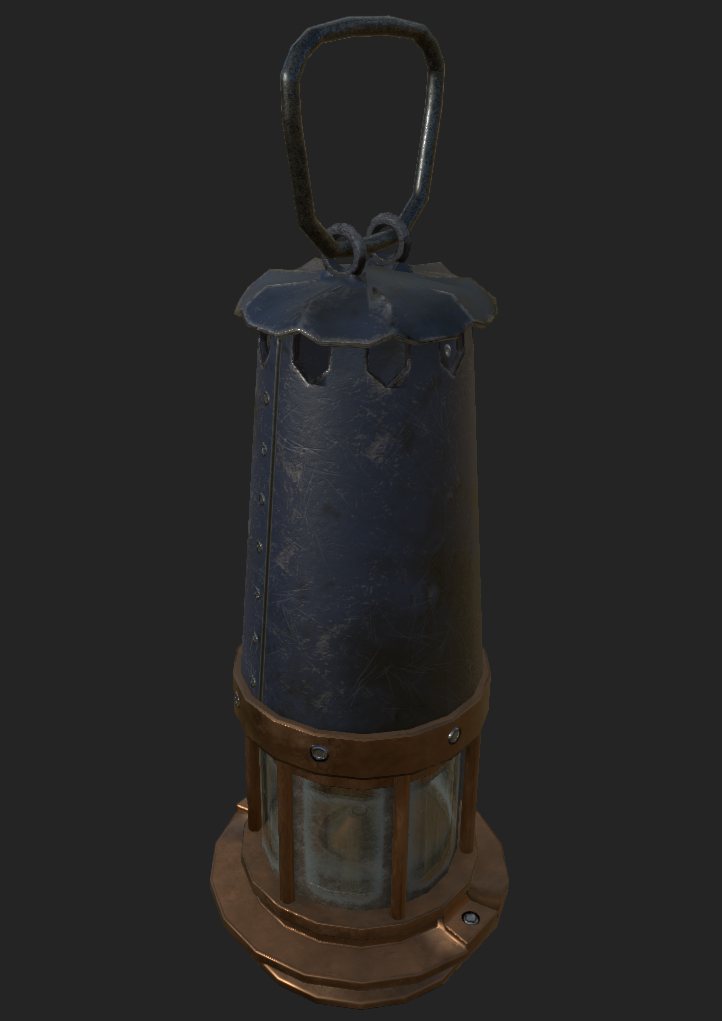
A Miner’s Lamp model
This model has a cylindrical area which will contain the light. The position of the light is specified by a socket (which the Point Light component will be attached to inside Unreal.)
The expectation would be for the light produced by this to be blocked in a cylinder at the top and the bottom, and to have six small vertical bars of shadow where the support beams are.
Creating a cubemap for the light mask
We will need to create a cubemap to act as a mask for which sides of the lamp are obstructed.
The cubemap will effectively be a 360° view from the position of the light source, with white for the angles at which the light escapes the lamp and black for the angles where is obstructed.
I created the cubemap for the lantern by making a copy of the model and placing it inside a sphere with flipped normals.
I painted the model itself with a pure black material, and the sphere with a pure white one. (I also subdivided and smoothed the mesh to make the shape of the shadow more rounded than the actual in-game model.)
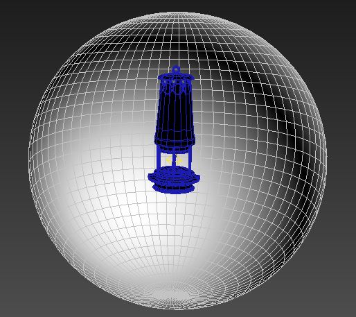
Setting up a scene for capturing a cubemap
The cubemap needs to be created from the point on the model where the light will originate – in this case, I created it from the socket that I placed in the model for the flame position.
Most 3D modelling packages should have the capability to create a cubemap for a specific point in 3D space. The exact procedure to create a cubemap will depend on the chosen application.
Regardless, the process should result in a set of six images, one for each face of the cube: Back, down, front, left, right, and up.
The images need to be arranged into a cube-cross image, using the following format:

A cross view of a sample cubemap with labelled sides
The following Windows batch script will use IrfanView to rotate and place the six images of the cubemap into the appropriate cross position.
It assumes that the input images are named as follows (replace baseFilename with the appropriate name of for the cubemap.):
- baseFilename_LF.png – Left
- baseFilename_RT.png – Right
- baseFilename_BK.png – Back
- baseFilename_FR.png – Front
- baseFilename_UP.png – Up
- baseFilename_DN.png – Down
(To use this, modify the path to IrfanView as appropriate for your system.)
@echo off
set iview="C:\Program Files (x86)\IrfanView\i_view32.exe"

%iview% %1_LF.png /bright=-255 /convert tmp_0.png
%iview% %1_LF.png /rotate_l /convert tmp_1.png
%iview% %1_RT.png /rotate_r /convert tmp_2.png
%iview% %1_BK.png /rotate_r /rotate_r /convert tmp_3.png
%iview% %1_FR.png /convert tmp_4.png
%iview% %1_UP.png /rotate_r /rotate_r /convert tmp_5.png
%iview% %1_DN.png /rotate_r /rotate_r /convert tmp_6.png
%iview% /panorama=(2,tmp_0.png,tmp_2.png,tmp_0.png,tmp_0.png) /convert tmp_a.png
%iview% /panorama=(2,tmp_3.png,tmp_5.png,tmp_4.png,tmp_6.png) /convert tmp_b.png
%iview% /panorama=(2,tmp_0.png,tmp_1.png,tmp_0.png,tmp_0.png) /convert tmp_c.png
%iview% /panorama=(1,tmp_a.png,tmp_b.png,tmp_c.png) /convert %1_cubecross.png

del tmp_0.png tmp_1.png tmp_2.png tmp_3.png tmp_4.png tmp_5.png tmp_6.png
del tmp_a.png tmp_b.png tmp_c.png
Save as MakeCubeCross.cmd and run from the command line with:
MakeCubeCross basefilename
(You can also make the “cube cross” manually using your favourite image editing tool.)
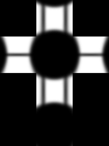
The cube cross for the miner’s lamp looks like this:
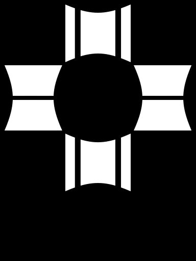
The cross view of the cubemap for the Miner’s Lamp
Next, open AMD CubeMapGen.
The interface of this tool is filled with a lot of buttons and it is a bit confusing.
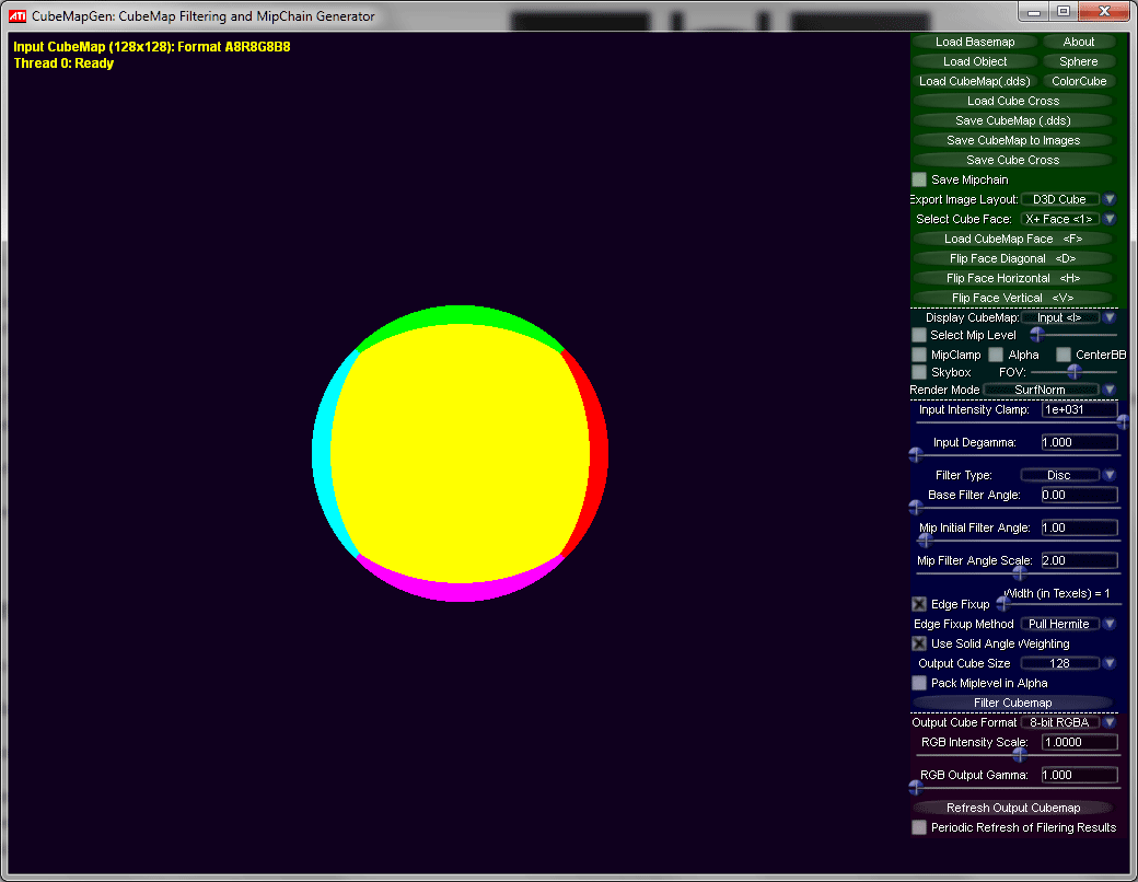
The CubeMapGen interface
Select the “Load Cube Cross” button near the top of the panel on the right, and open the cube cross file.
Wait for a few moments for it to load.
Near the bottom of the panel, there is an Output Cube Size setting; configure that to an appropriate size. Small sizes (such as 128) might be sufficient for simple shapes, though you may need to go higher if the shape has a lot of round edges. I chose 512 for the lamp model.
Select “Save CubeMap (.dds)”, pick a filename, and save the resulting DDS file, ready to be imported into Unreal.
Leave CubeMapGen open for now, as you’ll need it again later.
Setting up the basic light function in Unreal Engine
Open Unreal, import the cubemap dds, and then create a new Material for the light function.
On the Details panel, change the Material Domain to Light Function. A light function material only has one pin – for Emissive Colour.
Create a Texture Sample, select the cube map texture, and drag the output into the Emissive Colour on the material.
Create a Light Vector node. This gives the coordinates of the light, and will be used to feed into the UV of the texture sample.
However, it appears to always be mis-rotated by 90°, so create an MF_RotateVector_90 node.
Hook the Light Vector Node into its input, and hook its output CW Y into the UVs of the texture sampler.
The completed material should look something like this:
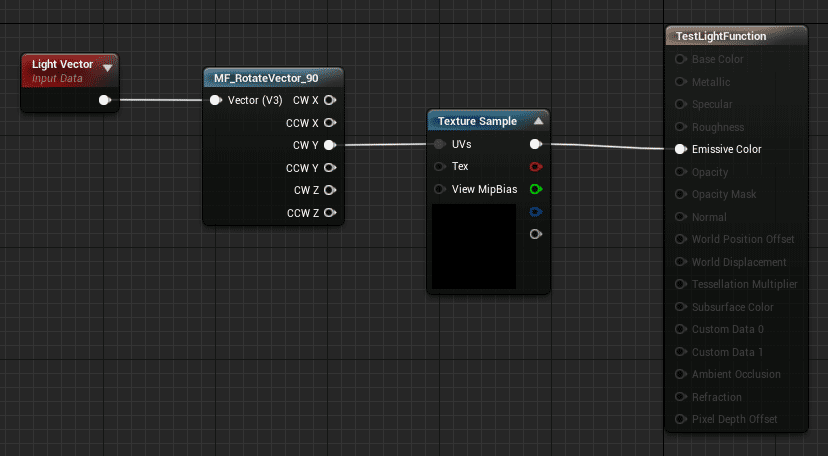
Simple light function material
The next step is to set up the lamp’s blueprint.
Add a Static Mesh component for the lamp, and create a point light under it, with the appropriate parent socket.
On the Point Light, scroll down the properties panel to the Light Function section, and select the newly created material as the Light Function Material.
The rest of the properties don’t matter for this effect, though you might want to adjust the intensity, attenuation radius, and possibly turn on Ray Traced Distance Field Shadows.
To make sure that the engine shadows don’t interfere with the fake, masked ones, make sure to turn Casts Shadows off on the lamp mesh.
(This does, unfortunately mean that no other light source will be to cast shadows of the lamp, but that should be fine in most cases. You may want to toggle the shadow casting back on at any time that the lamp is turned off.)
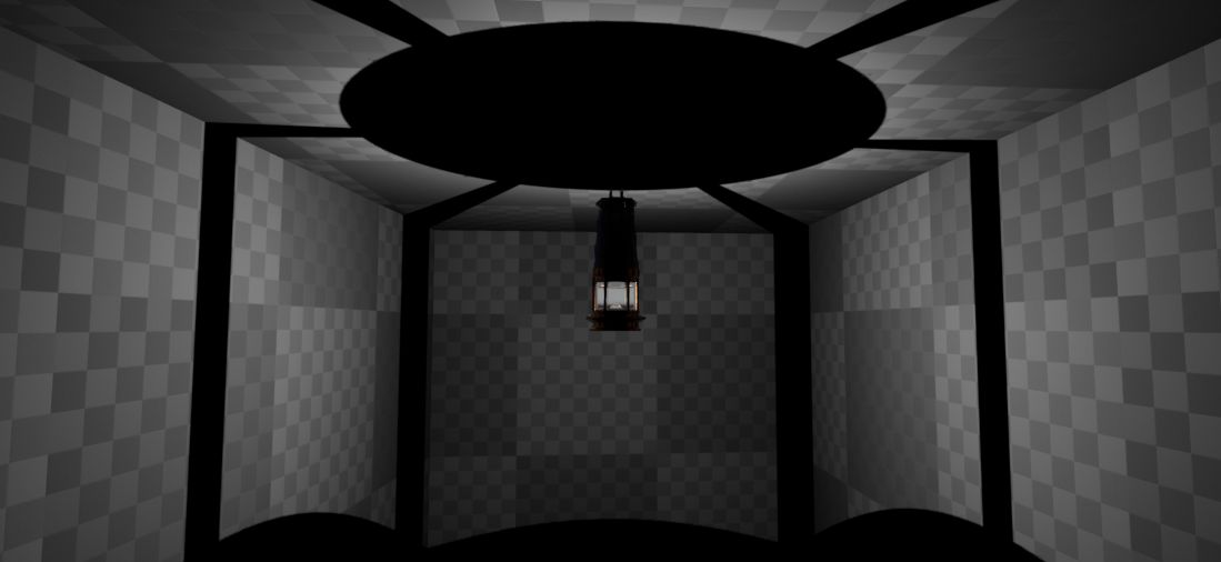
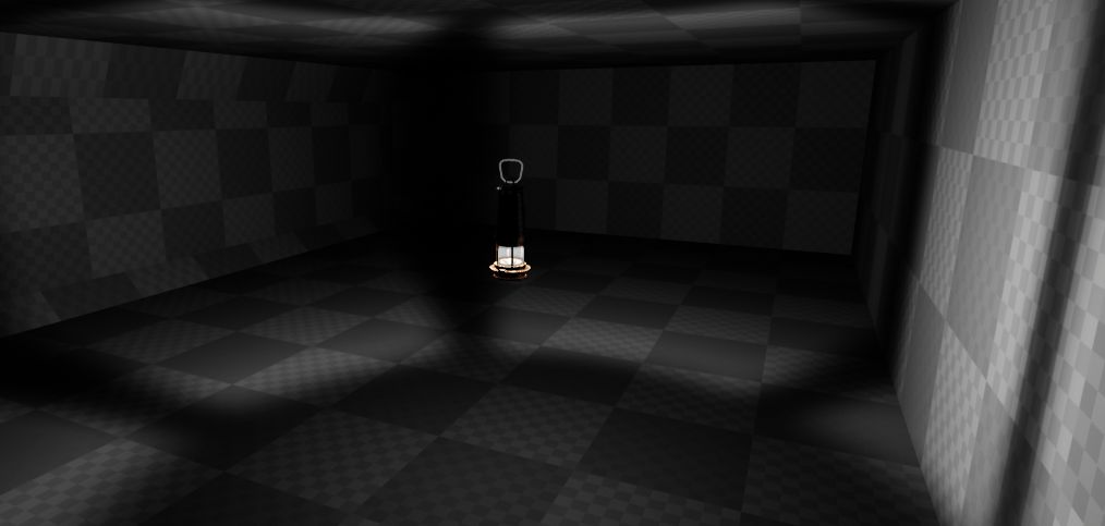
The “shadows” cast by the simple light function, as they appear in-game.
Here is the effect in-game. Notice how the cast shadow is very sharp and harsh.
There are two issues here.
The first is that the shadows remain extremely crisp, with hard edges, regardless of the distance. Those shadows should get softer and less defined the farther away from the light they are.
The second is that the shadowed areas are pitch black. Realistically, there’d be enough light scatter from the surrounding surfaces to provide at least some illumination even in places that are obscured by the shadows.
We’ll deal with the sharp shadows first.
The idea here is to fade between two different cube maps based on the distance from the light, so that the shadows close to the light will be sharp, while those farther away will be much softer.
Creating a second cubemap to use at farther distances
Switch back to CubeMapGen, with the cube cross we created earlier loaded.
The blue part of the control interface is used to apply a filter to the cubemap.
Under Filter Type, select Gaussian to apply a Gaussian blur.
The Base Filter Angle is the amount of blur to apply. You will probably need to play around with this value to get the exact effect that you want. 10 is a good starting point.
Click the “Filter Cubemap” button near the bottom of the interface to apply the blur. Note that it will take several seconds to process (or minutes, depending on the level of blur and the size of the map), as indicated by the text at the top-left corner. The map shown in the display will be incomplete until it has finished.
The cross view of the blurred cubemap for the Miner’s Lamp
Once you are happy with the level of blur, save this second cube map as .dds.
Adding a distance-based blend to the second cubemap
To set up the distance-based facing, first import the second cube map into Unreal, and then go to edit the material we created earlier.
Add a second Texture Sample using the new cubemap, and plug the same wire (the rotation of the light vector) into the UVs of this one as well.
Add three Scalar Parameters and name them LightRadius, NearDistance, and FarDistance.
The light function only has access to the distance of the surface being struck as a range between 0 and 1, where 1 represents the maximum attenuation radius of the light source. In order to convert that into an actual distance, the LightRadius will need to be passed into the material.
The other two parameters are to allow the distances to be adjusted; anything below NearDistance will use purely the first (sharp) cubemap, while anything beyond FarDistance will use purely the second (blurred) cubemap, with anything between the two points using an appropriate fade between the two.
The suggested default values are:
- LightRadius: 1000
- NearDistance: 100
- FarDistance: 500
To set up the fading, grab the CW Y output of the MF_RotateVector_90, and plug it into a VectorLength node (use the V3 pins).
Then, set up the following sequence of mathematical operations:
((VectorV3Length * LightRadius) - NearDistance) / (FarDistance - NearDistance)
And then clamp the result to the range 0 – 1.
Finally, create a Lerp node between the sharp cubemap (A) and the blurred cubemap (B), using the result of the previous clamp as the alpha.
The result should look something like this:
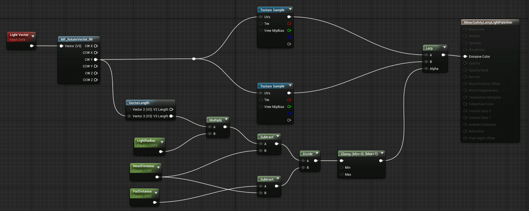
Light function material with distance-based fading between sharp and blurred textures
There’s one last step, which is to configure the lamp’s blueprint to push the radius of its light down into an instance of the material.
Set up the Construction Script of the blueprint to create a dynamic material instance of the light function, set its LightFunction parameter base on the light’s attenuation radius, and then apply it as the light function to the light.
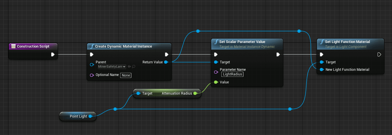
Construction script for lamp blueprint
Dealing with the dark shadows
The shadowed areas are still pitch black, which is easily fixed by applying a floor of light to the light function.
Create two new ScalarParameters and name them NearMinimumLight and FarMinimumLight.
Hook them up so that they are added to the output of the two texture samples before they are put into the Lerp node.
Suggested default values are:
NearMinimumLight: 0.01
FarMinimumLight: 0.10
The final graph should look something like this:
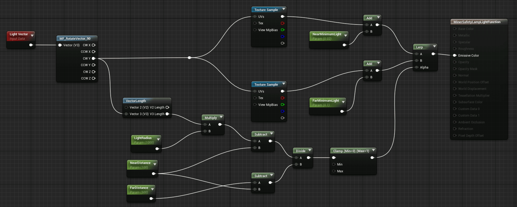
Final light function, with distance-based fading between sharp and blurred, and minimum light levels for shadows
The result
The final effect, in game, should look like this:

Leave a Reply